Project 02 · hardware & teleoperation
GELLO-YAM Assembly and Teleoperation
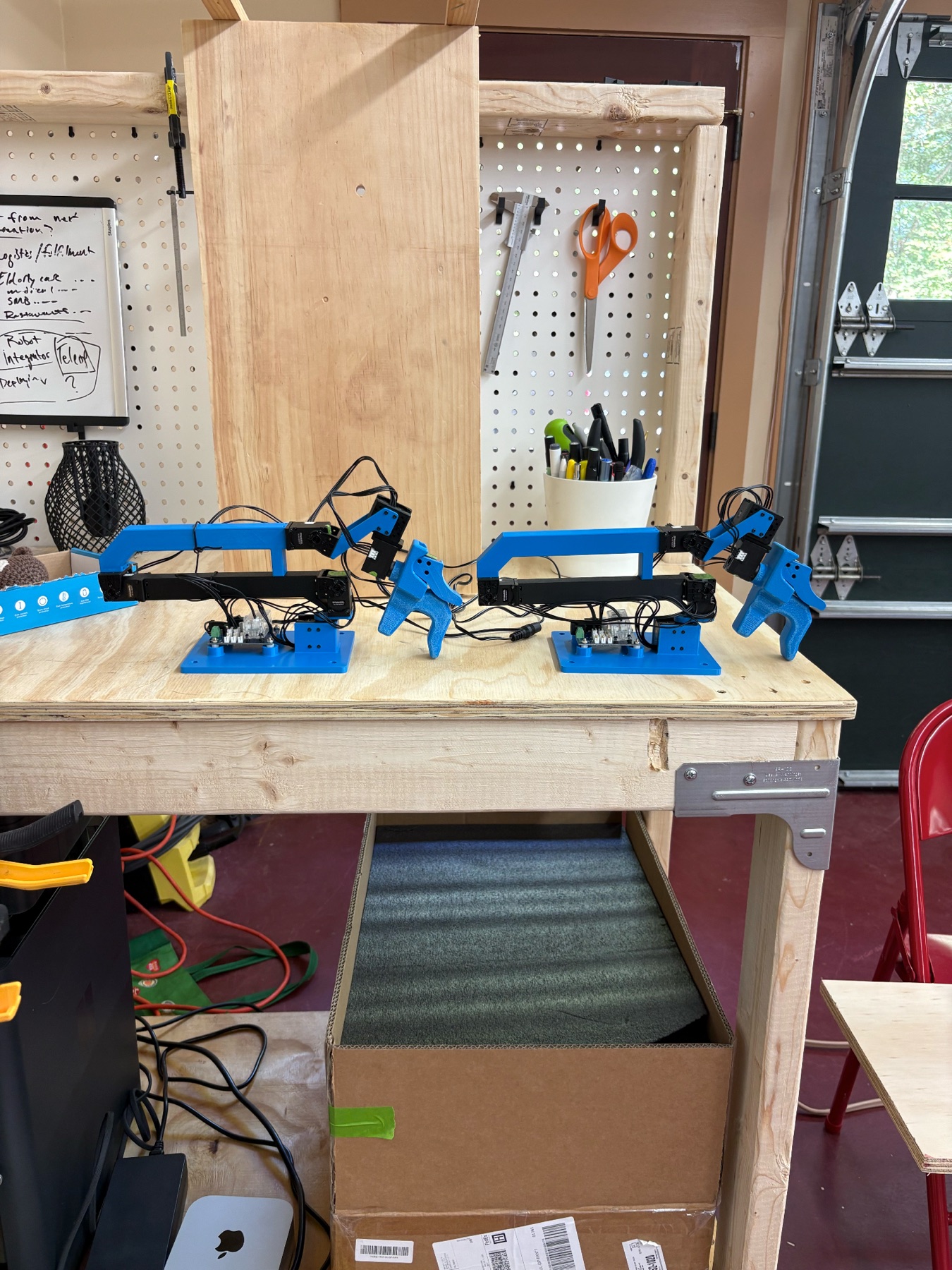
Building the GELLO arms
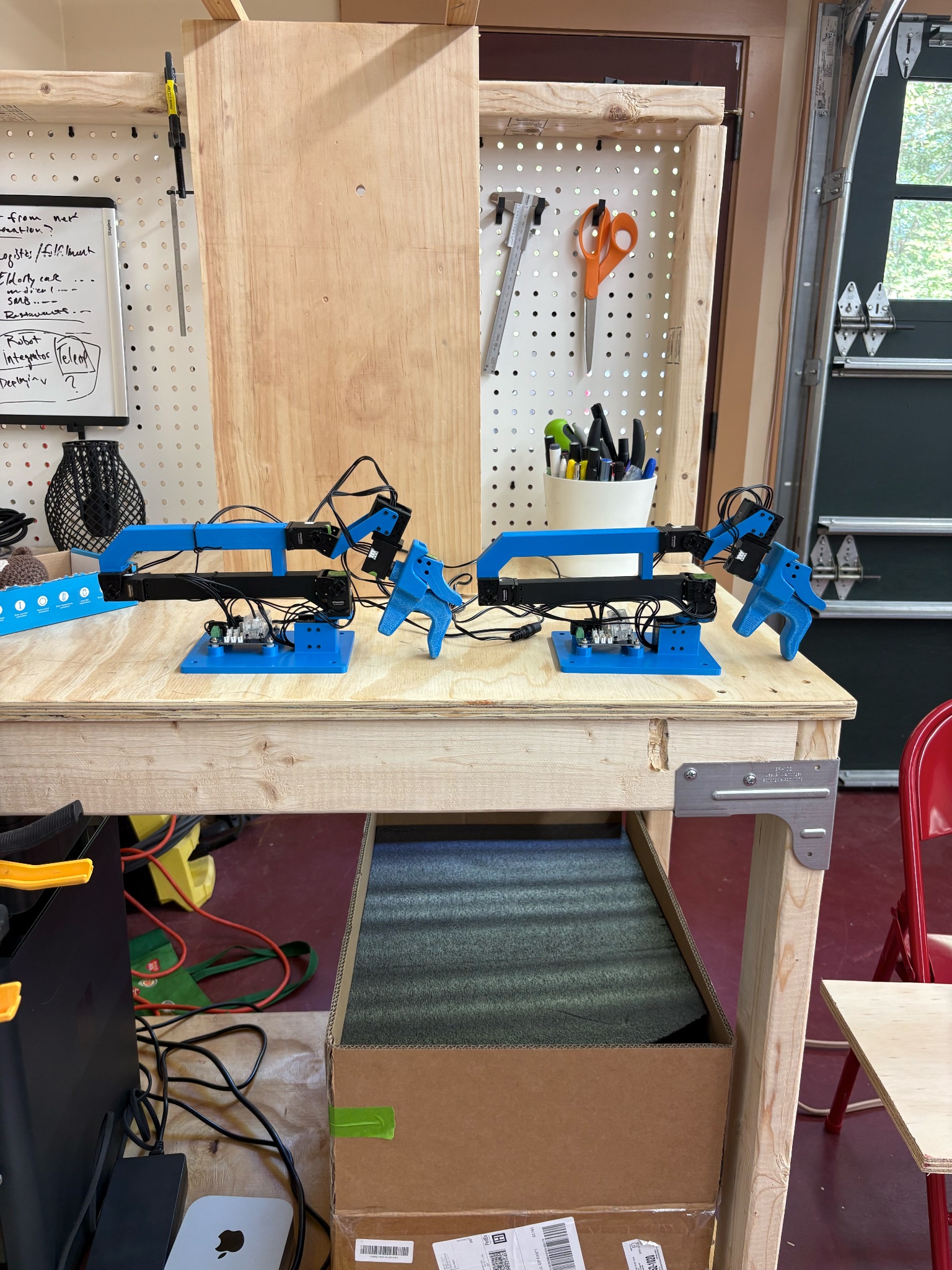
My second project I completed included two different parts, assembling two small YAM GELLO passive arms and connecting and performing teleoperation between the GELLO arm and the YAM arm via an anvil dev box. In order to build the GELLO arms I first had to order all 14 motors (12 XL330-M288-T and 2 XL330-M077-T), 2 power adapters, wires and hardware (these came inside the packets with the motors and powerboards), 2 U2D2s, and 2 U2D2 power boards. All of these materials I ordered from Robotis, a robotics company that specializes in robot innovation. In addition to ordering these parts I also had to 3d print the structural components of the arm. The GELLO components can be found under GELLO mechanical created by wuphilipp on GitHub. I uploaded the components from GitHub to BambuStudio, a 3d printing software, and then began printing the parts.
I printed the parts in three batches with each batch taking around 10-12 hours. Once the parts were printed, I still had one more step before I could begin constructing the arms, programming and IDing every motor. In order to do this I had to download a program called DynamixelWizard2. Once the program was downloaded, using a USB cord I connected a U2D2 to my computer. I then connected the U2D2 to the U2D2 power board using a three pin wire. Then I plugged two three pin wires into the U2D2 power board and then plugged their other ends into the motor. The final step was to plug the power adapter into the U2D2 power board. But unfortunately I had ordered the wrong voltage power adapters where if I had used the ones I had originally purchased it potentially could have fried those motors. So due to this I had to go to a local tech store and see if they had the right adapters. But unfortunately none of the barrels on their adapters fit into the barrel socket on my power board. Luckily there was a small plus minus wire box on my power board, so we stripped the new adapters cord in order to expose the wire. We tested for the positive and negative end using a benchtop multimeter, in order to avoid putting the wires in the wrong slot, which would have caused an explosion.
Now that the power board finally had power I was able to begin programming and IDing the motors again. For each motor, on Dynamixel, I would first scan it, then ID it, and lastly I would check the motors LED lights and torque. After everything was IDed and confirmed to work, I would disconnect the motor and physically label it with tape and a pen for assembly later. I repeated this for all 14 motors making sure to label which ones were for which arm. After all the motors were complete I began assembling the first arm.
Unlike when you build a lego set there were no build directions or instructions that I could follow. All I had to go off was which screws went in where and an overall picture of the final build. I sorted my screws by length (4 mm, 6 mm, and 8 mm) and the 4 mm by color into black and silver. The black were used to screw directly into the motors plastic horn or the 3D printed part. While the silver screws would be attached to silvers nuts. All of the screws and nuts listed above were M2. I started with the second motor and attached the first 1st 3D printed piece to the motor using a motor mount. I continued up the chain of motors until I reached the gripper installation. Then I moved down to base assembly. I had originally not started with the base and motor 1 due to how bulky it was and the fact that I would need to be able to move the arm around while assembling it as the hardware I was using was extremely small. In order to be able to place the hardware in correctly I used a pair of small tip tweezers and a magnetic screwdriver.
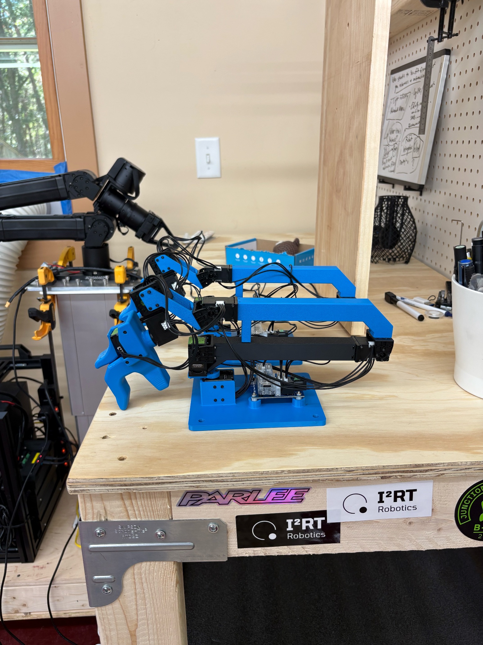
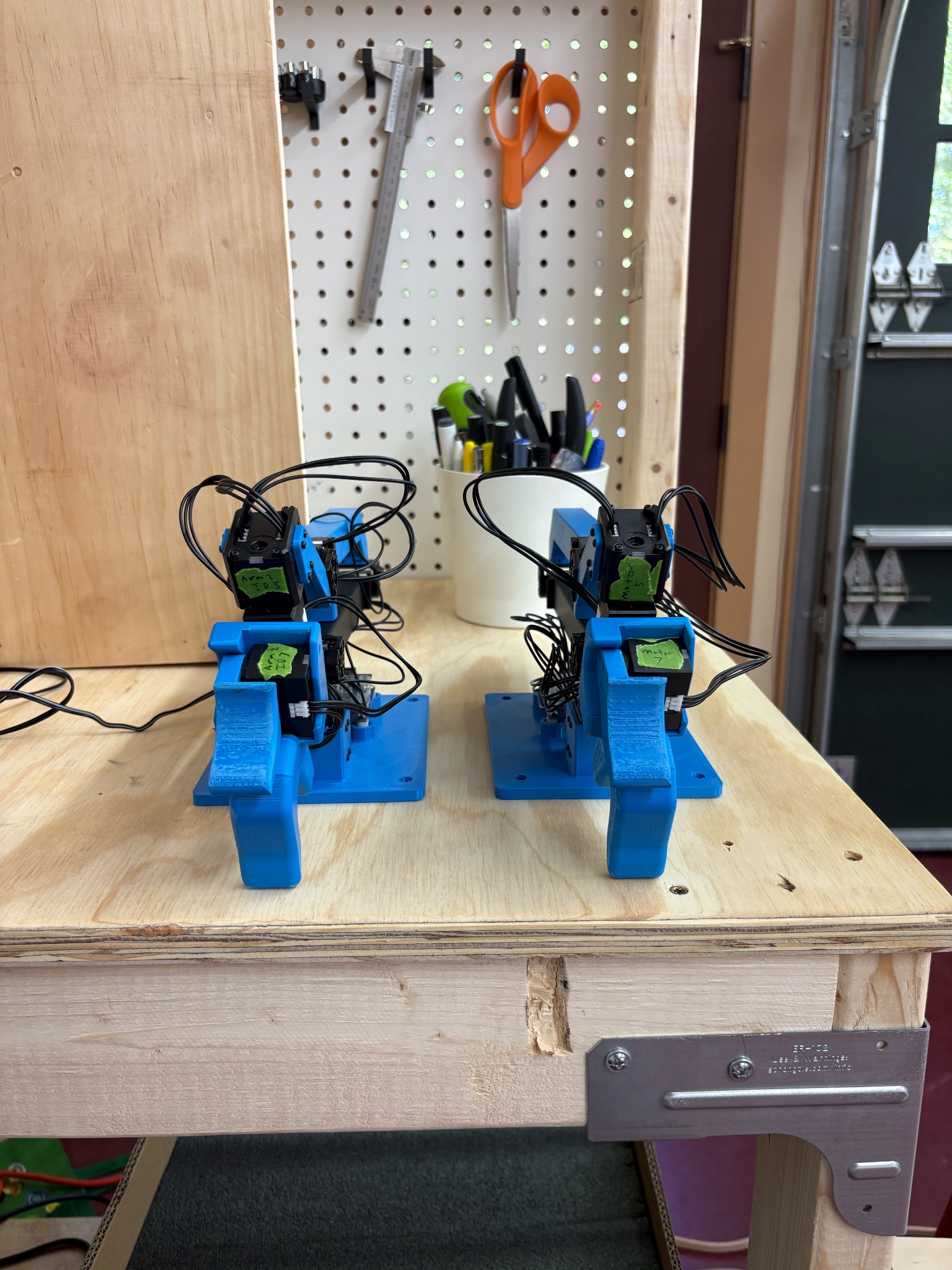
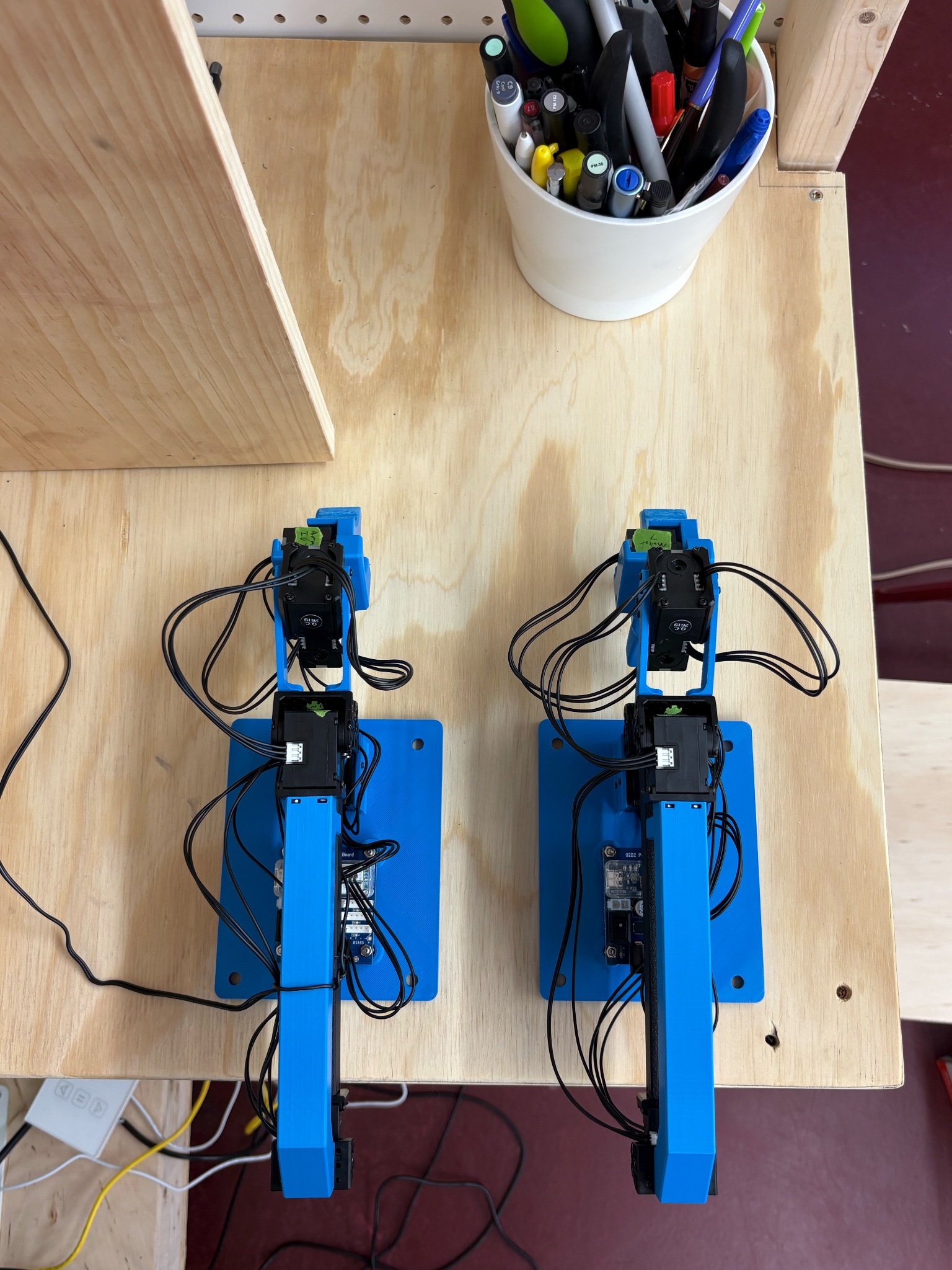
Once the base was assembled and connected to the arm, it was time to assemble the gripper and connect it to the arm. The only problem was that the image I was going off of did not have the gripper attached. Additionally, there was nothing online that I could find to go off of. So I called Robotis to see if they had any completed pictures of the arm so I could see how to assemble and connect the gripper to the rest of the arm. With Robotis’s support I was able to finish the rough build of the arm. With the arm fully constructed all I had left to do was connect all the servos on the motors and attach the U2D2 and power board to the base. I Daisy chained the wires together and secured the power board to the base using M3 8 mm screws and then attached the U2D2 to the power board. I then completed an initial check by powering up the arm and connecting the U2D2 to my computer to see if the LED lights on the motors would flash to show that they were all connected. Every motor flashed successfully, I then repeated the assemble process again for the second arm.
Out of everything I did this summer at Breth this was by far and away the project that I had the most fun doing. Getting to use my hands and assemble these robots without any instructions could get insanely frustrating at times but the feeling of finally getting a piece in the right place or completing a part of the arm made all of the frustration and anger so worth it. Being able to build something with your own hands and to go through the trials and tribulations that come with it, the sense of accomplishment you feel when you finally finish is unmatched.
Teleoperation with the YAM arm
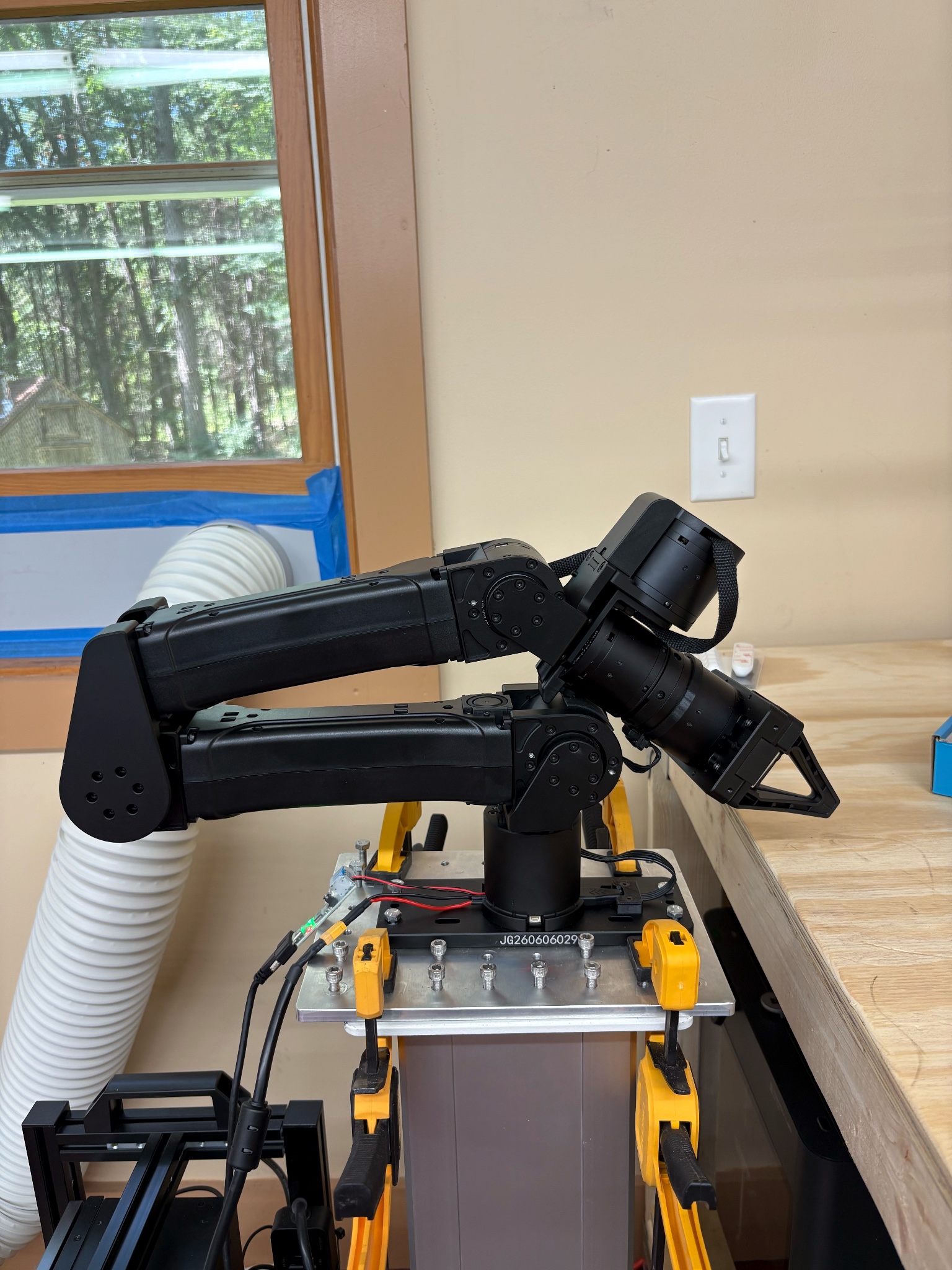
Once both arms were built I moved onto setting up teleoperation between the YAM arm and the GELLO arm. The GELLO being the leader and the YAM being the follower arm. I connected both arms to the Anvil dev box, along with the U2D2 on the GELLO arm, plugged in the power adapter to the power board, and then SSH connected my computer to the Anvil dev box in order to speed up the process of the setup and future teleoperation. The first step in setting up teleoperation was confirming that all seven motors were communicating with the dev box. Once this was confirmed I calibrated the YAM arm’s joint positions and recorded the endpoints for the gripper. After calibration was complete, I then matched the YAM and GELLO arm starting positions and saved these positions as their home positions. So that after the end of a teleoperation task the YAM would be able to return to the same starting position when given the go to home command. Additionally, Codex was able to keep track of the exact degree that each joint position was at while at the home position. Therefore before starting teleoperation I would be able to check if the GELLO arm was in the correct position matching that of the YAM. Matching the leader arm and follower arm during teleoperation is crucial. Without doing this, matching movements is extremely challenging and getting good data for machine learning is impossible.
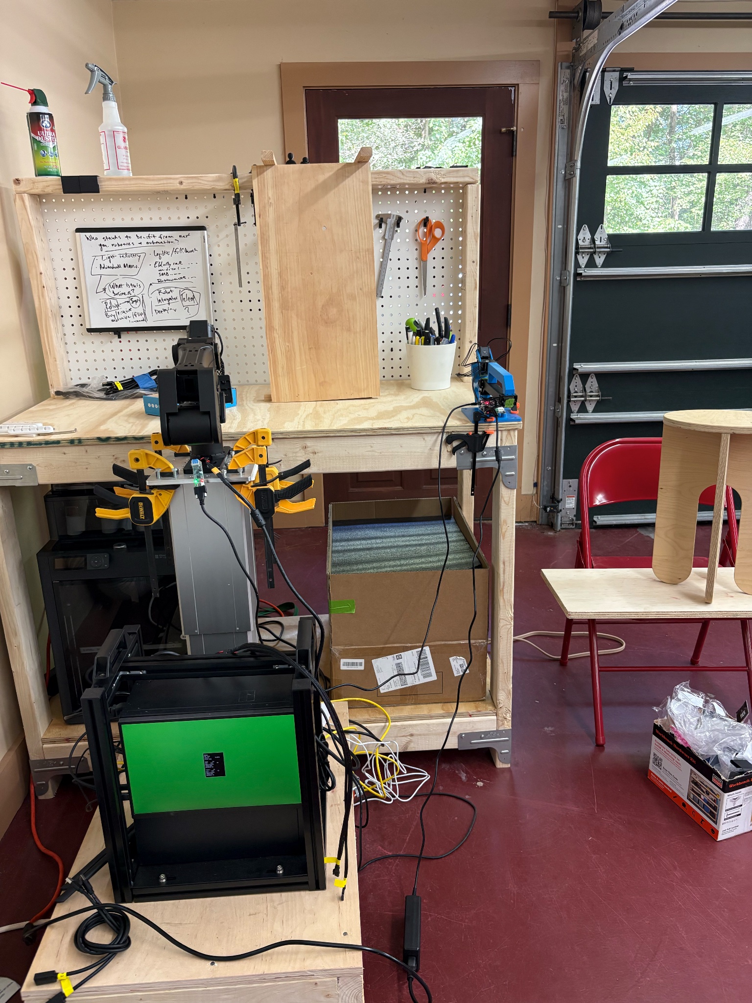
The next check was to see if the direction and offset of each motor so that every movement the GELLO arm made the YAM arm was able to follow its exact movement. Following this, I performed my first test on the arms running a zero movement test. This test verifies encoder readings, CAN communication, temperatures, and motor status of the YAM arm. The next test I performed I moved each motor individually keeping the range of motion under 30 degrees for each joint. I started with motor J1 (The first indexed motor in the base) and worked my way up to the gripper (J7).The test was continuous and once I moved one motor I then would return it to its home position and then move the next motor. This test ultimately had a lot of failed attempts due to the fact that the configuration of the GELLO arm did not allow for certain motors to move by themselves. For instance when J2 (Joint 2) would move J4 (Joint 4) would also have a small bit of movement. So in order to pass this test I allowed for the test to be able to move certain motors at the same time. Additionally another problem I ran into during this was the conservatism of Codex. Codex is very cautious when running these tests and when doing any teleoperation, so because of this it contains preset limits that the YAM arm is not allowed to exceed. These limits include range of motion, speed, and temperature values. Every time a limit is passed the YAM arm will shut down and the test will be immediately regarded as a failure. I ultimately wanted to pass the tests within the limits but after an onslaught of failed attempts I discarded the limits and successfully passed the test.
With all motion and tracking successful without any signs of stuttering or inconsistency during the tests it was time for full teleoperation. At first I practiced moving the arm around in simple ranges of motion and then began to test its extreme ranges. Following this I began to try and run a pick and place with the same brown ball from the SO-101 arms project. Initially the movements with the YAM and GELLO arms were extremely different from that of the SO-101 arms. The leader arm for the SO-101 arm was slightly heavier and had a much shorter body. Additionally its joints were stiffer, especially the gripper’s motor. While the GELLO leader arm was able to reach farther along the table and movements in general felt cleaner and smoother compared to that of the SO-101 leader arm. Although the leader arms are very different, comparing their differences to the differences of the two follower arms makes the two leader arms look the same. The YAM follower arm is about triple the size of the SO-101 arm. The YAM’s gripper is significantly stronger than that of the SO-101 arm. Finally the SO-101 is small enough to be able to reset it manually when it is turned off, the parts of the YAM are very heavy and motors extremely strong makes the YAM arm impossible to manually reset to home. This is another reason why I used Codex to create a return to home procedure. Even if the motors were disabled it would still be extremely difficult for me to manually return the arm to its home position due to the weight and size of the YAM arm. Thus trying to complete the pick and place task posed some serious challenges at first with the YAM and GELLO arms. As I had become accustomed to the much smaller and lighter SO-101 arms. After a few trials I finally got the motion down. Since the GELLO leader arm was also much lighter than the YAM follower arm, slowing my movements down on the GELLO so they moved at the same speed was key to finally reaching success. But once I got the hang of the movements and how the arm worked, it moved and operated ten times smoother than the SO-101 arms.
I was able to finish the project just at the end of my summer at Breth, wrapping up a successful build and teleoperation set up. In the future if I had more time I would have liked to have collected data on the pick and place task using the YAM and GELLO arms and then build a policy off of that data. Seeing how this policy and the ones I made for the SO-101 arms would have been a really interesting comparison and great data to use in future studies or projects.